
Drawings Description UNDERSTAND THE DRAWINGS WHICH HELPS YOU BUILD THE DESIGNS
#1. Column Center Line Drawing
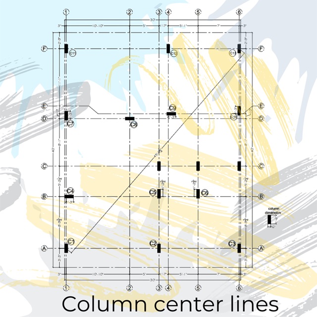
#1. Column Center Line Drawing
This drawing focuses on the significance of columns in construction. It's a crucial step that determines the structural integrity of the building. The column center line DWG provides essential details for column placement, including the number of columns needed, column dimensions, and precise location on the site. These details are essential for initiating the construction process.
#2. Floor Plan Working Drawings
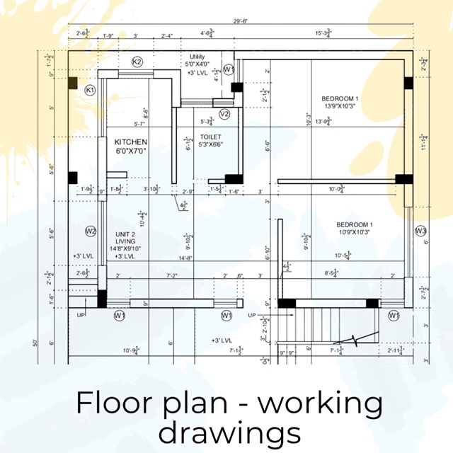
#2. Floor Plan Working Drawings
Floor plan working drawings encompass crucial details concerning walls, windows, and more. They provide comprehensive information necessary for construction, such as wall thickness, materials, heights, and the precise locations of windows and doors. Additionally, these drawings convey the placement and dimensions of the staircase, ensuring accurate implementation on-site.
#3. Sections - 2D
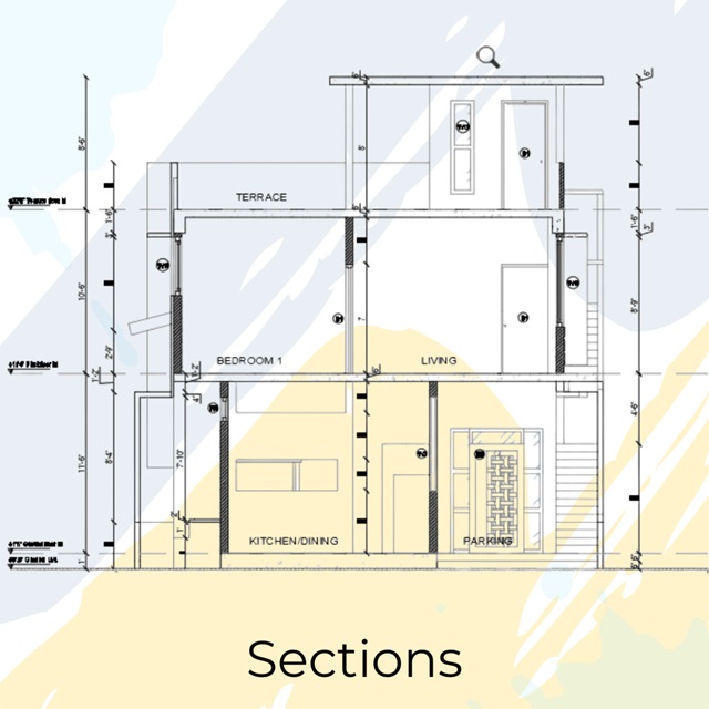
#3. Sections - 2D
A comprehensive 2D section provides valuable information, including floor-to-floor heights, sill and lintel heights for windows, staircase landing heights, and openings within interior walls. This drawing also reveals details about double heights within the structure, as well as wall and roof heights, offering a comprehensive understanding of the design.
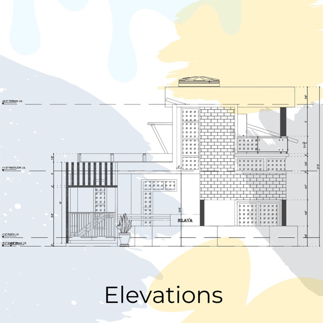
#4. Elevations - 2D
#4. Elevations - 2D
This drawing will illustrate the dimensions of the external cladding, in accordance with the design. It will provide information about the various elements incorporated at different heights, including their thickness and material specifications. Additionally, details about railings, parapet heights, compound designs, gate designs, and other relevant information can be obtained from this drawing. Doors and windows detail dwg.
#5. Doors & Window Details
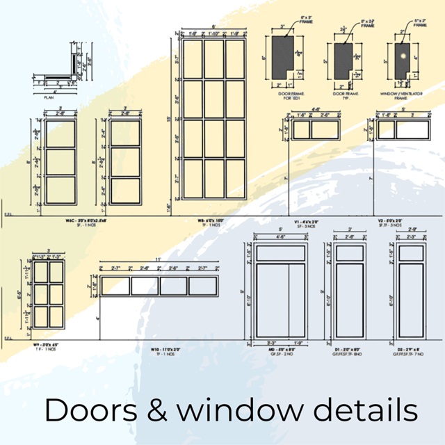
#5. Doors & Window Details
This drawing focuses on the various styles of doors and windows featured in the design. It provides precise dimensions for the doors and windows, along with the height at which the windows are situated from the finished floor level. Additionally, it specifies the thickness of the frames and shutters according to the design. The drawing also indicates the location of fixed windows as well as windows that can be opened.
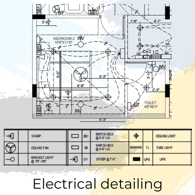
#6. Electrical Layouts
#6. Electrical Layouts
The electrical drawing serves as a guide for electricians, indicating the precise locations for lights, fans, AC switchboards, and the necessary controls for each appliance. It specifies the number of switches required and the corresponding controls to be installed at those points. The drawing also highlights the placement of ceiling lights, outlets for appliances like geysers and microwaves, and other relevant points. The legend provides clear representations of each electrical point, making it convenient for electricians to plan ahead before the casting of slabs.
#7. Plumbing Layout
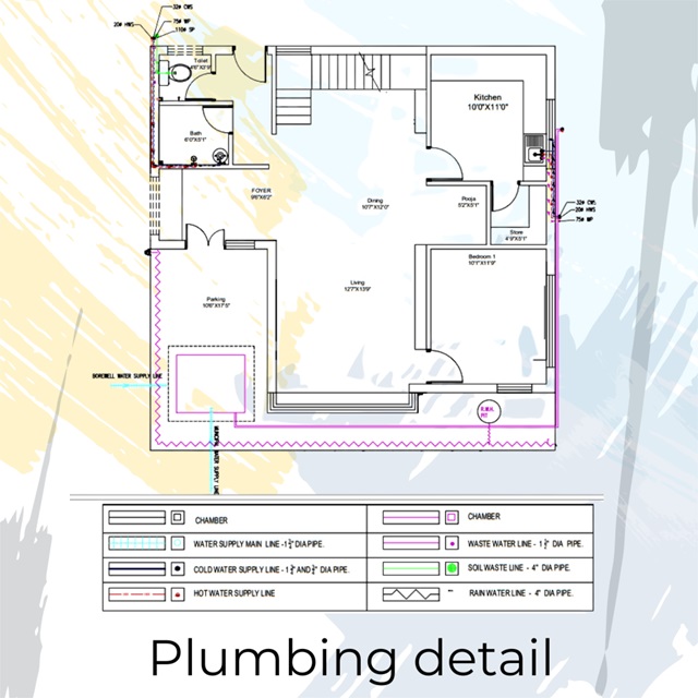
#7. Plumbing Layout
The plumbing drawing illustrates the placement of essential fixtures such as bath areas, WC, and washbasins in the toilets. It also indicates the location of the overhead tank and sump. The drawing showcases the direction of water flow from the overhead tank and sump in the ground floor. Furthermore, it outlines the entry and exit points for fresh water and sewage in the toilets and kitchen. The drawing provides a comprehensive plan, specifying the required capacity for water storage in the sump and overhead tank.